A number of legacy data centres were designed for 10G application where the backbone was based on MPO 12-fibre connectors. The previous version of the TIA standard (TIA-568-C3) described three basic connectivity methods A, B and C, which all companies adopted and implemented into their projects over time. The situation became more difficult when companies designed data centres for 40G and 100G and designed backbone networks with MPO connectors with 24 fibres.
TIA definitions and terms
TIA-568-C3 described component types and connectivity methods only for MPO 12-fibre connectors, not for MPO connectors with 24 fibres. Therefore, companies invented their own harness types and connectivity method standards which are not compatible with each other. In October 2016, the Telecommunication Industry Association (TIA) released a new update of the TIA 568.3-D standard, which, among other things, defines the rules for MPO connectors with 24 fibres.
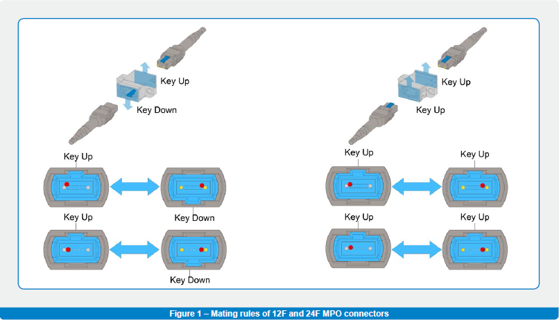
The TIA 568.3-D standard specifies the following components: Array adapter type, Array cable type and Array patch cord type. Two adapter types are specified: Type-A (KEY UP/KEY DOWN) and Type-B (KEY UP/KEY UP), which determine connection of fibres within two mated MPO connectors. Figure 1 shows the fibre connections on mated 12-fibre and 24-fibre MPO connectors.
Array cable type and array patch cord type harnesses are terminated on both ends by MPO connectors. The difference is only in the usage within an optical channel. An array cable is used as a backbone cable – used for connection between racks, patch panels and MPO-LC modules. An array patch cord type is used to start or end an optical patch from and to the transceivers. A combination of them is used to connect different types of transceivers, where each of them has a specific design and position of Tx and Rx channels. For proper functionality, designated types of array cables and patch cords have to be used as defined in TIA 568.3-D and listed in Figure 2.
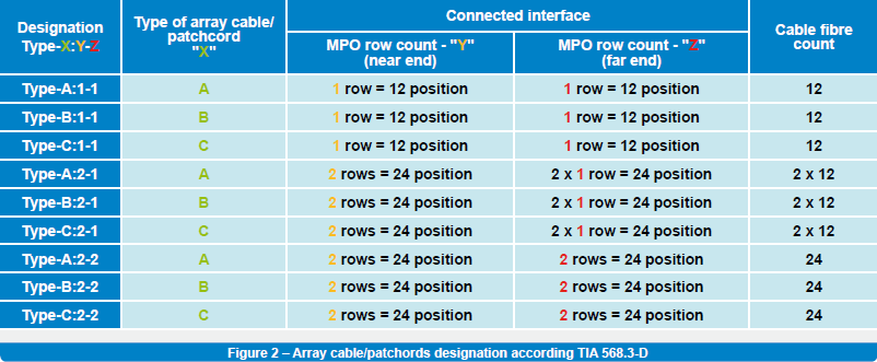
The first three rows show designations for array cables and patch cords with MPO 12-fibre connectors, and the next three rows are dedicated to array cables and patch cords on one end with MPO 24-fibre connectors, and on the other end with two MPO 12-fibre connectors. The last three rows describe designations where MPO connectors with 24-fibres are used on both ends of the array cables or patch cords. While in the case of 12F based systems (used for 10G applications) , there is a clear link between the well-known connectivity methods A, B, C and new designations Type-A: 1-1, Type-B: 1-1 and Type-C: 1-1, it starts to get more complicated when MPO 24-fibre connectors are used. In this white paper we will focus further on arrays and patch cords with MPO 24-fibre connectors on both ends.
Nomenclature mess
MPO connectors with 24 fibres have been known and used for many years, but as mentioned previously, due to the lack of a standard describing types of cables and connectivity methods, companies invented their own standards. They used different names like Straight, Cross, Vertically crossed and Horizontally straight, or they just simply used designations like Type A, B, C, Z, Y, X, etc… None of these names or designations was clear enough for customers and a great deal of confusion was created.
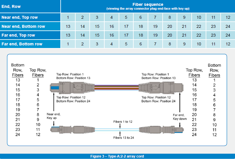
Before the release of the TIA 568.3-D standard, Sylex used the connection logic from 12-fibre MPO connectors and applied it to 24-fibre MPO connectors. As an example, let’s take the 12F Type A patch cord: a fibre from position ONE on the near end is connected to position ONE on the far end. Sylex also applied this logic to MPO 24-fibres, so a fibre from position ONE on the near end (top row) was connected to position ONE on the far end (top row); all other fibres were connected in the same way – up to the position 24 fibre on the near end (bottom row), which was connected to position 24 on the far end (bottom row). Sylex named this connection Type A for array cables and patch cords with 24-fibre MPO connectors.
To properly interconnect the CXP/CFP/CPAK interfaces, Sylex introduced the Type X patch cord, within which the top row on the near end is connected to the bottom row on the far end (position 1 is connected to position 13, position 12 to position 24).
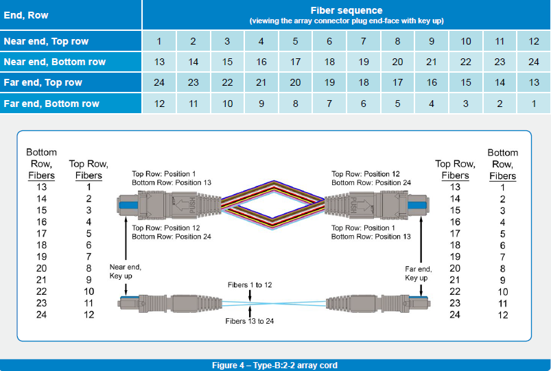
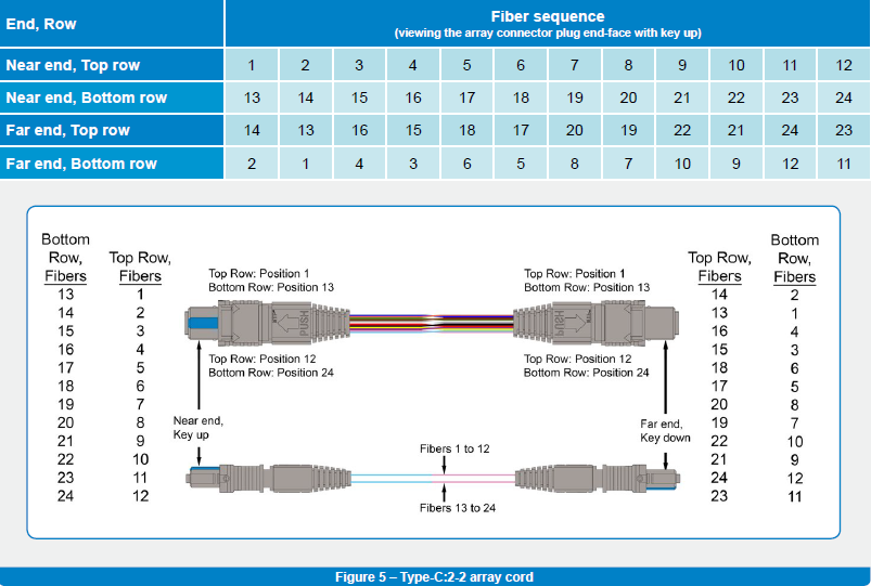
The new TIA 568.3-D standard definition for array cables and patch cords with MPO 24-fibre connectors is shown in detail in Figures 3, 4 and 5. As you can see, Type-A:2-2 does not fit to Sylex Type A, but to Sylex Type X. Sylex Type A for MPO 24-fibre arrays and patch cords is even not covered in TIA 568.3-D.
As a conclusion, we can say that in order to prevent any connectivity issues with products based on MPO 24-fibre connectors, companies should either refer to the TIA 568.3-D standard or clearly define a wiring diagram on a drawing. Sylex polarity methods, either for 12- or 24-fibre MTP® assemblies, can be found at https://www.sylex.sk/documents/technical-support-documents.html
Connectivity methods vs. protocols
Besides different array and patch cord cable types, the TIA 568.3-D standard also defines the different connectivity methods (polarities), which show a combination of array patch cords, array cables and adapters to create a connection between transceivers. The designation of the connectivity methods follows the same approach as in the case of types of array cords: A, B and C. At first sight it looks clear, but there is hidden a potential problem in case MPO 24-fibre connectors are chosen.
The main problem is in understanding which Tx and Rx channels within the transceivers should be interconnected. As shown in Figure 6, the typical 24F transceiver has all the Rx channels in the TOP row and all the Tx channels in the BOTTOM one.
The numbering of the channels is from RIGHT to LEFT. This follows the numbering rule of the MPO / MTP connector. Looking at the front face of the MPO connector with its key up, the TOP LEFT position is marked as No.1. (see Figure 1) Once the connector’s front face is turned towards the adapter in the transceiver, position No.1 of the connector matches the position (fibre) No.1 of the transceiver.
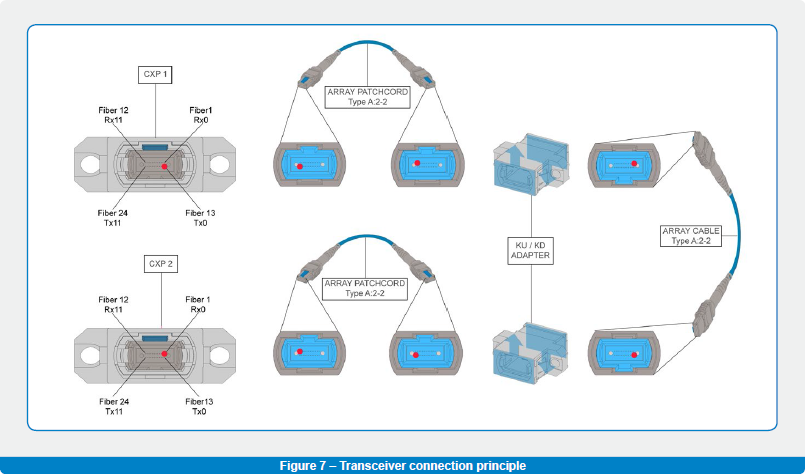
The transceivers’ interconnection follows a fundamental principle: to connect channel Tx0 on the near end to channel Rx0 on the far end. An example of a two-point connection for the 24F transceivers is visible in Figure 7, where Tx0 – position No.13 on the near end is connected to Rx0 – position No.1 on the far end, using a Type A:2-2 patch cord.
However, in Annex C the TIA 568.3-D standard defines connectivity method ““A””, which links two different fibre positions /ports together: Tx0 – position 13 on the near end with Rx11 – position 12 on the far end.
To compare:
TIA standard defined connection: Tx0 -> Rx11
Fundamental principle based connection: Tx0 -> Rx0
Using two other connectivity methods described in TIA 568.3-D, connectivity method B and C, will result in the same situation – Tx0 in position 13 on the near end is interconnected with Rx11 in position 12 on the far end.
This difference can lead to serious issues during the definition of the array cables and patch cords that should be used in the planned installation, as ETHERNET and INFINIBAND protocols work differently as regards signal routing.
In the case of Ethernet protocol, the signal mapping has a kind of intelligence which ensures that the signal transmitted from the near end will be properly received on the far end. In practice it is sufficient to set up only a cross connection between the TOP (Rx) and BOTTOM (Tx) rows of the transceivers. Once the signal is physically switched from TOP to BOTTOM and vice versa, the link intelligence takes over the proper routing from Tx0 to Rx0.
On the other hand, the INFINIBAND protocol does not have this kind of intelligence and the mapping has to be done directly on the hardware level. It means a real physical connection should be created between Tx0 and Rx0.
This fact implies the conclusion that in the case of Ethernet based systems, any of the TIA 568.3-D defined connectivity methods can be used, while for Infiniband Tx0 to Rx0, channels have to be physically connected – see Figure 7.
Based on this observation, it is much safer to choose the connectivity method according Figure 7 as it is not known in every instance whether Ethernet or Infiniband is used in the real running service.
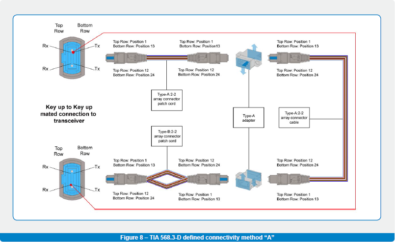
On top of that, establishing a typical 2-point connection defined by TIA (Figure 8) requires the following:
- two pieces of Type-A:2-2 array cords
- one piece of Type-B:2-2 array cord
- two pieces of Type-A adapters
Establishing the same connection based on fundamental principle (physical connection from Tx0 to Rx0) requires:
- three pieces of Type-A:2-2 array cords
- two pieces of Type-A adapters
It is obvious that the second option is more suitable from the inventory and planning point of view.
Nuts and bolts
- Always contact the harness supplier and agree on:
- the terminology used for array cables
- the terminology used for the adapters
- the terminology of wiring and connectivity methods
- Have in mind the complete fibre path from the transmitter to the receiver:
- patch cables
- PnP modules and their inside connectivity
- array patch cords and array cables
- fanout / hydra products
- adapters – Key Up / Key Down or Key Up / Key Up
- MPO connector genders
- Be aware of difference in multimode and singlemode connectivity. Singlemode MPO connector (angle-polished) can be used only with the Key UP / Key Down adapters
- Consider the potential migration to next-generation networks
- Keep in mind the different approaches for Ethernet and Infiniband
The best way is to consult all details of your network with us and we will recommend a complete solution for you which is both easily deployable and futureproof.
Annex
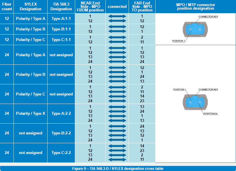
Cross table between Sylex and TIA 568.3-D array patch cords and array cable types.
Eduard Koza – R&D Manager – Contact
Eduard Koza is R&D manager at Sylex. He started as a project engineer for high-performance copper harnesses. In 2000, he widened his activities to passive fiber optic interconnection products and fiber optic sensing systems. At the beginning of this period, he mainly led multiple technology transfers and covered the implementation of new products into the company portfolio.
Later, he held the role of Engineering manager in the company and headed the technology and engineering activities responsible for transferring customer ideas to the final products. His current position covers the management of newly introduced technical solutions, utilizing his consultancy skills related to customized fiber optic interconnection products.